Hi,
these steps describes how to install Tasmota on Shelly Smart Home WIFI/WLAN relay.
First you need a the flash tool esptool. Simplest way is to install the python module. This is the same way on linux and windows
michael@debdev ~ # python3 -m pip install esptool
I use it in an virtual python environment so it is independend from the pythons host installation. There are two more steps. You have to install python venv one time.
michael@debdev ~ # sudo apt install python3-pip python3-venv
Then create a virtual environment and switch to it
michael@debdev ~ # python3 -m venv /home/michael/esptool-env
michael@debdev ~ # source /home/michael/esptool-env/bin/activate
Now, install esptool in your virtual env, the esptool is only useable when you are in this environment.
(esptool-env) michael@debdev ~ # python3 -m pip install setuptools wheel
(esptool-env) michael@debdev ~ # python3 -m pip install esptool
You can leave the virtual env by the deactivate command and go back with the source /home/michael/esptool-env/bin/activate.
For the flashing process you need a serial RS232 interface. If your computer does not have one use a USB to RS232 TTL device like this. Note you need TTL level at the RS232 site and not a SUB-D connector.
NOTE: !!!!! THE SHELLY MUST NOT BE CONNECTED TO THE 230V MAIN VOLTAGE/SUPPLY DURING FLASHING: THERE IS NO ISOLATION BETWEEN THE MAIN VOLTAGE AND THE ESP!!!!! The 3.3V Supply from the USB RS232 Converter is sufficent for flashing.
Wire the converter like this:
Connection RS232 to Sheely
_____________________
|                    \
|                     \
|                GND  |
|             GPIO 0  |
|              RESET  |
|               3.3V  |
|                RxD  |
|                TxD  |
|                     /
|____________________/
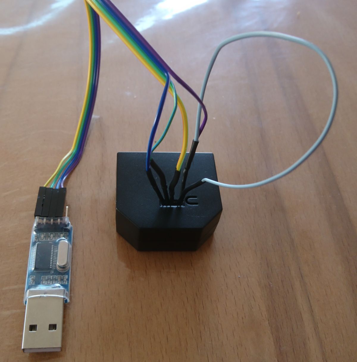
The grey wire is a bridge from GND to GPIO0 to enable flash mode.
Enter flash mode: Connect GPIO 0 to GND and power on. GPIO 0 can be set to GND during the whole flush process.
Test Connection. Read MAC and determine flash size:
(esptool-env) michael@debdev ~ # esptool.py -p /dev/ttyUSB0 read_mac
esptool.py v2.8
Serial port /dev/ttyUSB0
Connecting....
Detecting chip type... ESP8266
Chip is ESP8266EX
Features: WiFi
...
(esptool-env) michael@debdev ~ # esptool.py -p /dev/ttyUSB0 flash_id
...
Manufacturer: 5e
Device: 6014
Detected flash size: 2MB
Staying in bootloader.
Note if a command is not working pull the USB RS232 and plug again.
If you are on Windows use the COM Port instead of /dev/ttyUSB0.
Backup the original firmware
Switch to flash mode as descripted above (shortened GND and GPIO0)
(esptool-env) michael@debdev ~ # esptool.py -p /dev/ttyUSB0 --baud 115200 read_flash 0x00000 0x200000 Backup_shelly_org_2MB.bin
If you want to restore the original firmware use
(esptool-env) michael@debdev ~ # esptool.py erase_flash
(esptool-env) michael@debdev ~ # esptool.py -p /dev/ttyUSB0 --baud 115200 write_flash 0x00000 0x200000 Backup_shelly_org_2MB.bin
To flash Tasmota get the latest version from the Tasmota release page. Usually tasmota.bin. There are also localized version. For example the german version tasmota-DE.bin. Also special versions for example with knx support: tasmota-knx.bin. When I wrote this post 8.4 was the latest release.
(esptool-env) michael@debdev ~ # wget https://github.com/arendst/Tasmota/releases/download/v8.4.0/tasmota.bin
Erase the flash memory and flash the firmware
(esptool-env) michael@debdev ~ # esptool.py erase_flash
(esptool-env) michael@debdev ~ # esptool.py  --baud 115200 write_flash -fs 1MB -fm dout 0x0 tasmota.bin
Note: The internal LED does not work anymore after flushing tasmota.
Tasmota wrote some status information to the serial terminal at 115200 Baud. To take a look at these messages use screen or minicom. Note: This is difficult with USB/RS232 devices for boot messages, because /dev/ttyUSB0 is just available until the adapter is plugged in and tasmota boots really fast. But further message will give hints for some issues.
(esptool-env) michael@debdev ~ # screen /dev/ttyUSB0 115200
00:06:16 WIF: Connect failed with AP timeout
00:06:16 RSL: stat/tasmota_D7DCFE/RESULT = {"POWER":"ON"}
00:06:16 RSL: stat/tasmota_D7DCFE/POWER = ON
00:06:17 WIF: Connecting to AP1 MyWiFi in mode 11N as sonoff-garage...
00:06:31 WIF: Connect failed with AP timeout
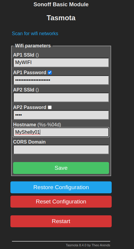
When tasmota is installed it provides an WiFi WLAN with name tasmota_deviceid_xxxx. You can connect without a password/key. When connected open a Browser and navigate to http://192.168.4.1. You can use the Scan for WiFi Networks at the top of the page.
Enter your WiFi Parameters and restart tasmota. After the reboot it should connect to your WiFi. Then you have to determine the new IP Address by taking a look to your WiFi Router.
Connect again by openeing the browser and enter the new IP Address
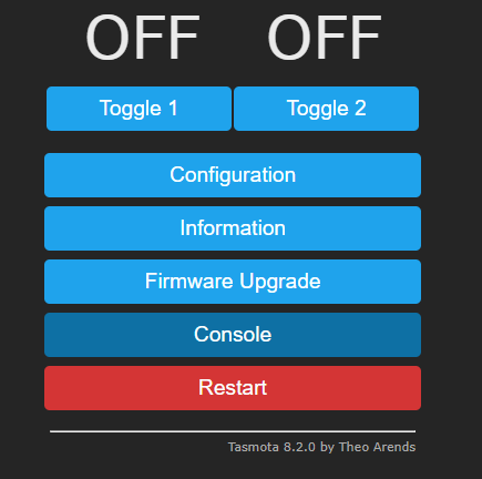
Then you have to configure to enable the shelly specific function in Tasmota. Go to
Go to Configuration – Configure Other and paste the template into the template field, check activate and press save.
{"NAME":"Shelly 2.5","GPIO":[56,0,17,0,21,83,0,0,6,82,5,22,156],"FLAG":2,"BASE":18}

Thats it.
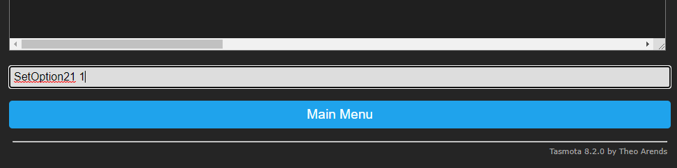
Shelly can measure voltage and frequency of the main supply. This can be enabled by the tasmota console. Note: This disables serial logging, because the energy chip uses the same serial interface.
Set SetOption21 1
A command reference can be found here.
The energy measurement has to be calibrated see the tasmota project page for more details.
If you want to enable MQTT. Open the config page. Enter Host, Port, Username and password of your MQTT Broker.
Topic path example:
Topic = tasmota_%06X

Full Topic = shelly/%prefix%/%topic%/
This results in an Topic path for commands
shelly/cmnd/tasmota_B91207/POWER2
or telemetrie data
shelly/tele/tasmota_B91207/STATE
To switch relay 1 on send
shelly/cmnd/tasmota_B91207/POWER1 1
michael@debdev ~ # mosquitto_pub --topic shelly/cmnd/tasmota_B91207/POWER1 -u MyBrokerUser -P 'BrokerPW' -h 10.254.10.20 -p 1883 -m 1
Michael
Sending commands with MQTT , WebAPI or the Webconsole (Main Menu -> console)
If you want to see Voltage and Frequency also when the relays are off, use SetOption21 1
MQTT
FullTopic=shelly/%prefix%/%topic%/
Topic=tasmota_%06X
then the state and sensor publish path is
shelly/tele/tasmota_B93B07/STATE
shelly/tele/tasmota_B93B07/SENSOR
the command state path
shelly/stat/tasmota_B93B07/RESULT
To set Relais On publish
shelly/cmnd/tasmota_B93B07/POWER1 1
–>