these steps describes how to install Tasmota on Sonoff Smart Home WIFI/WLAN relay.
First you need a the flash tool esptool. Simplest way is to install the python module. This is the same way on linux and windows
michael@debdev ~ # python3 -m pip install esptool
I use it in an virtual python environment so it is independend from the pythons host installation. There are two more steps. You have to install python venv one time.
michael@debdev ~ # sudo apt install python3-pip python3-venv
Then create a virtual environment and switch to it
michael@debdev ~ # python3 -m venv /home/michael/esptool-env
michael@debdev ~ # source /home/michael/esptool-env/bin/activate
Now, install esptool in your virtual env, the esptool is only useable when you are in this environment.
(esptool-env) michael@debdev ~ # python3 -m pip install setuptools wheel
(esptool-env) michael@debdev ~ # python3 -m pip install esptool
You can leave the virtual env by the deactivate command and go back with the source /home/michael/esptool-env/bin/activate.
For the flashing process you need a serial RS232 interface. If your computer does not have one, use a USB to RS232 TTL device like this. Note you need TTL level at the RS232 site and not a SUB-D connector.
Note: !!!!! It is not necessary to connect the sonoff ot the 230V main voltage/supply during flushing: There is an isolation between the main voltage and the esp but keep the risk as low as possinble The 3.3V Supply from the USB RS232 Converter is sufficent for flashing.
Wire the converter like this:
Sonoff TH10/16                        USB/RS232 Converter
----------                           ---------------------
     GND  | ----------------------- | GND
     RxD  | ----------------------- | TxD
     TxD  | ----------------------- | RxD
    3.3V  | ----------------------- | 3.3V
----------                           ---------------------
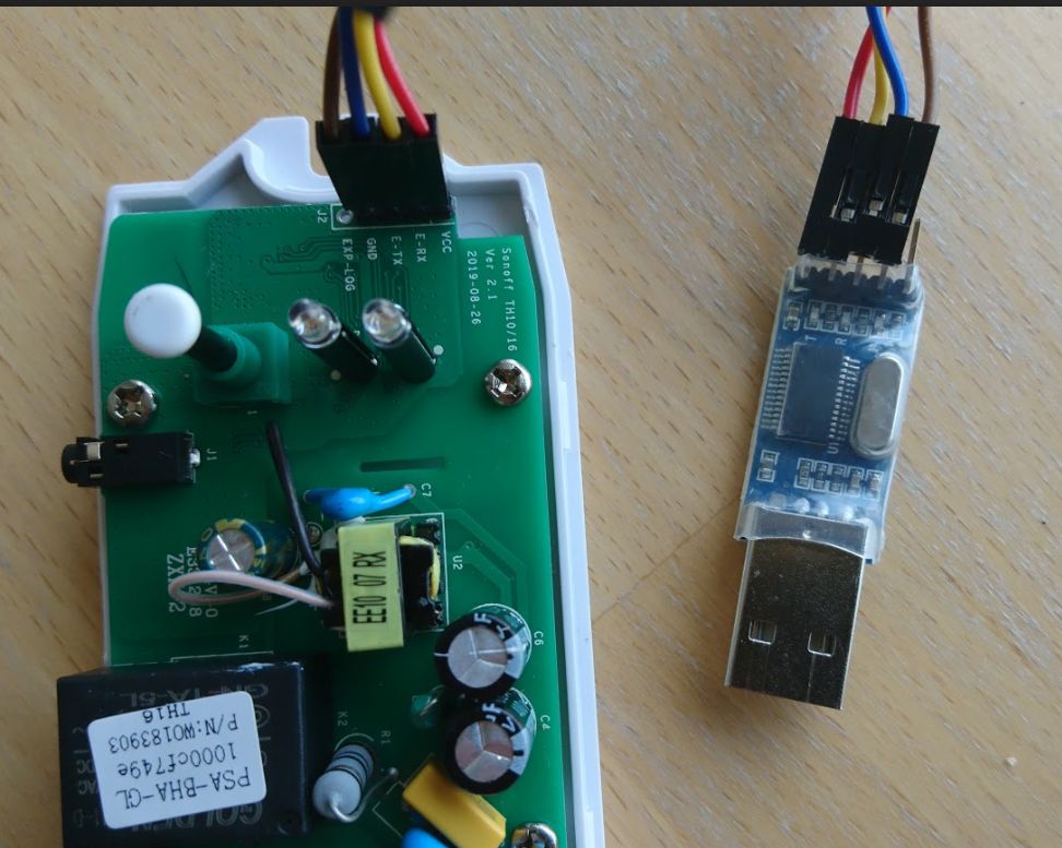
Enter flash mode: Hold the push button switch while plugin the USB/RS232 adapter. This shorten the ESP GPIO 0 to GND.
Test Connection. Read MAC and determine flash size:
(esptool-env) michael@debdev ~ # esptool.py -p /dev/ttyUSB0 read_mac
esptool.py v2.8
Serial port /dev/ttyUSB0
Connecting....
Detecting chip type... ESP8266
Chip is ESP8266EX
Features: WiFi
...
(esptool-env) michael@debdev ~ # esptool.py -p /dev/ttyUSB0 flash_id
...
Manufacturer: 5e
Device: 6014
Detected flash size: 1MB
Staying in bootloader.
Note if a command is not working pull the USB RS232 and plug again.
If you are on Windows use the COM Port instead of /dev/ttyUSB0.
Backup the original firmware
Switch to flash mode as descripted above (shortened GND and GPIO0)
(esptool-env) michael@debdev ~ # esptool.py -p /dev/ttyUSB0 --baud 115200 read_flash 0x00000 0x100000 Backup_sonoff_org_2MB.bin
If you want to restore the original firmware use
(esptool-env) michael@debdev ~ # esptool.py erase_flash
(esptool-env) michael@debdev ~ # esptool.py -p /dev/ttyUSB0 --baud 115200 write_flash 0x00000 0x100000 Backup_sonoff_org_2MB.bin
To flash Tasmota get the latest version from the Tasmota release page. Usually tasmota.bin. There are also localized version. For example the german version tasmota-DE.bin. Also special versions for example with knx support: tasmota-knx.bin. When I wrote this post 8.4 was the latest release.
(esptool-env) michael@debdev ~ # wget https://github.com/arendst/Tasmota/releases/download/v8.4.0/tasmota.bin
Erase the flash memory and flash the firmware
(esptool-env) michael@debdev ~ # esptool.py erase_flash
(esptool-env) michael@debdev ~ # esptool.py  --baud 115200 write_flash -fs 1MB -fm dout 0x0 tasmota.bin
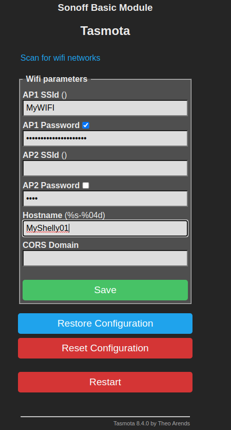
When tasmota is installed it provides an WiFi WLAN with name tasmota_deviceid_xxxx. You can connect without a password/key. When connected, open a Browser and navigate to http://192.168.4.1. You can use the Scan for WiFi Networks at the top of the page.
Enter your WiFi Parameters and restart tasmota. After the reboot it should connect to your WiFi. Then you have to determine the new IP Address by taking a look to your WiFi Router.
Connect again by openeing the browser and enter the new IP Address
Tasmota wrote some status information to the serial terminal at 115200 Baud. To take a look at these messages use screen or minicom. Note: This is difficult with USB/RS232 devices for boot messages, because /dev/ttyUSB0 is just available until the adapter is plugged in and tasmota boots really fast. But further message will give hints for some issues.
(esptool-env) michael@debdev ~ # screen /dev/ttyUSB0 115200
00:06:16 WIF: Connect failed with AP timeout
00:06:16 RSL: stat/tasmota_D7DCFE/RESULT = {"POWER":"ON"}
00:06:16 RSL: stat/tasmota_D7DCFE/POWER = ON
00:06:17 WIF: Connecting to AP1 MyWiFi in mode 11N as sonoff-garage...
00:06:31 WIF: Connect failed with AP timeout
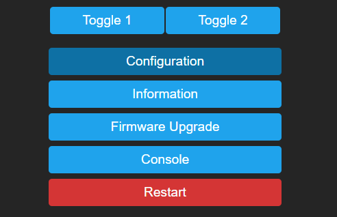
Then you have to configure the sonoff specific function in Tasmota. Go to configuration -> Configure Module

and set Sonoff TH (4)

Tasmota supports Sonoff TH with all three Sonoff sensors. And configure GPIO14 to the sensor you want to connect.

Depending on your temperature sensor it could be that you must configure the GPIO14 Pin to SI7021 instead of AM2301. This is due to the fact that the AM2301 Sensor has an has an additional protocol converter integrated, named SI7021.
Michael
Got it working, best instructions on internet 🙂
Excellent HowTo, Thanks !
On my debian, i had to call
apt install libssl-dev
before installing esptool.
I can confirm this still works great on the 2018 TH10 boards. One thing to note: My USB serial devices are cheap and have trouble registering, so it’s a pain in the butt to keep reconnecting. In that process I found a better way. Plug in the usb serial device until you see it registers with a lsusb command. then hook up everything except the 3.3v wire. Now just hold the device button down when you plug in the positive, and keep holding it till each process completes. When you finnish with a step, just pull the positive wire out again and let go of the button, next step, hold the button, plug it in 3.3v, keep holding till the flash completes, rinse & repeat. easy peasy 🙂